
- +1 (855) 956-3494
- / 9AM - 5PM EST / Monday-Friday
Technical support hours: 8AM – 8PM EDT, Monday – Friday
Welcome to the latest reference manual for Uniview's updated Graphical User Interface (GUI). You can use this blog in sequence with our video tutorial, we made it to be helpful for both visual and verbal learners. This master guide covers every single timestamp and feature from start to finish. Expand any chapter below to review complete operational procedures, menu pathways, and technical protocols. (Updated August 2026)
Uniview has overhauled its recorder operating system with a modern Graphical User Interface (GUI). This redesigned interface brings simplicity to navigation across display outputs and web browser management sessions.
If you have experience managing older Uniview firmware versions, the main changes lie in the consolidation of analytics and trigger configurations. The legacy "Smart" tab has been renamed to the "Events" tab. This holds all motion detection, Ultra Motion Detection (UMD), line crossing, and intrusion analytics rules.
Both the Local NVR Monitor Interface (connected directly to the recorder) and the Web Interface (accessed remotely over your local area network) now share an almost identical visual layout. This design choice ensures that configuring rules on a remote laptop presents the exact same menu paths and button placements as sitting in front of the physical NVR monitor.
Accessing the system via a computer connected to the same network router as the NVR. This method is ideal when the NVR is installed in a secure, hard-to-reach location such as a server rack, basement, or attic utility room.
Method 2: Direct Local Connection (Standalone Hardware Setup)
Connecting a mouse directly into the NVR's USB port and a monitor into the HDMI or VGA output port. This provides direct connection without requiring an active PC on site.
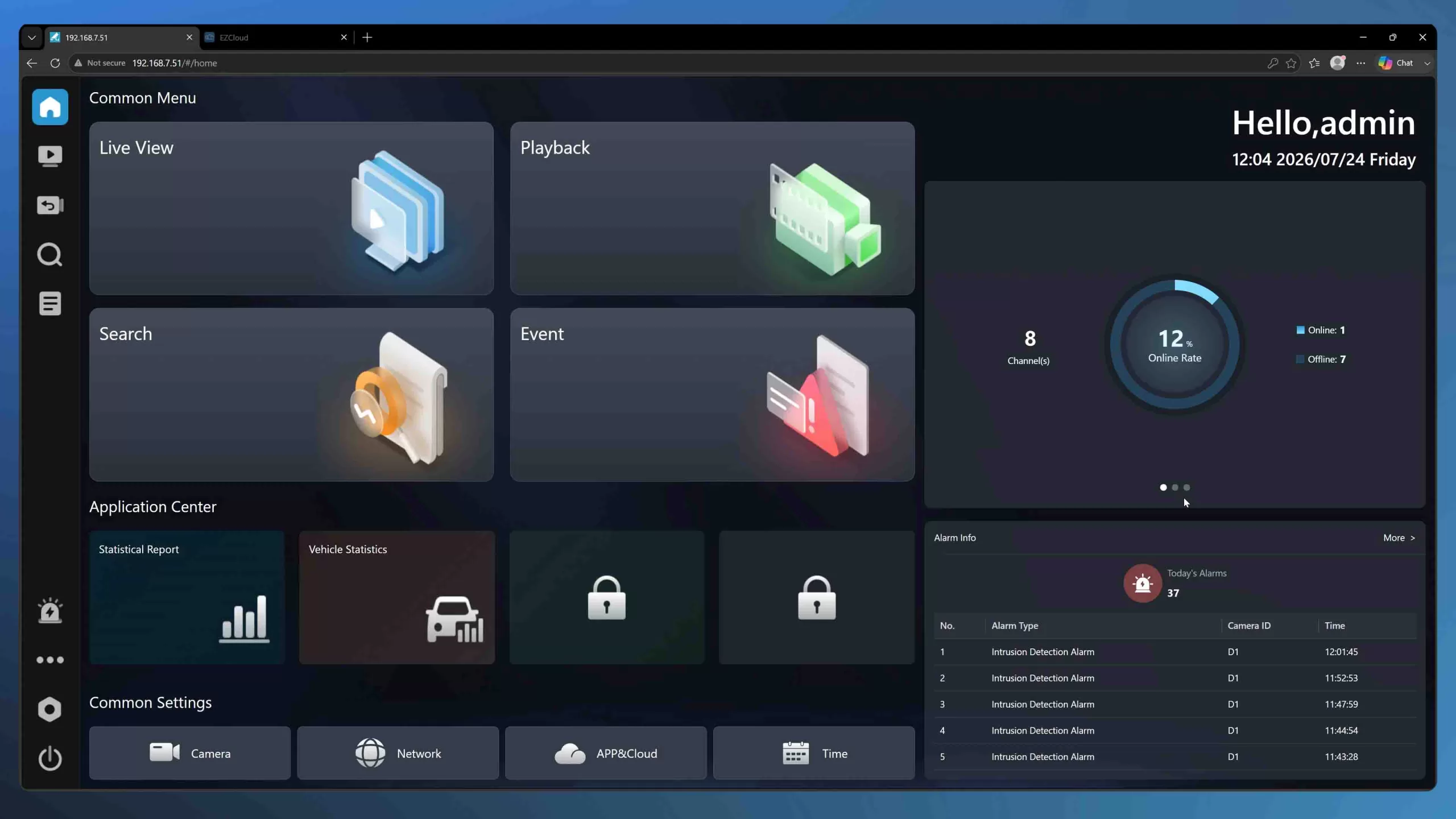 The redesigned Uniview GUI unifies the look and feel of local NVR monitor outputs and remote web browser sessions.
When launching the NVR web interface for the first time on your computer, specific web browser and authentication protocols must be established to ensure video streams display smoothly.
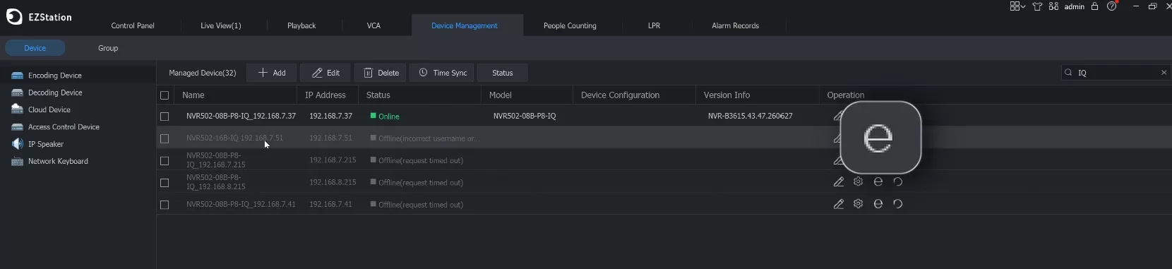 Locate the blue "e" icon or the pencil icon within the EZStation Device Management page.
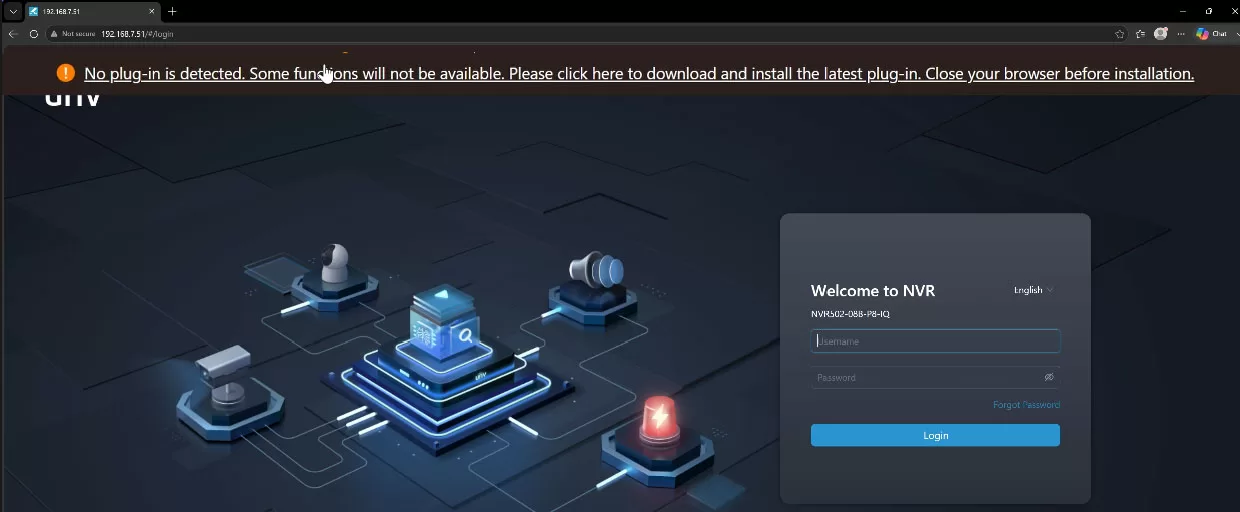 Install the requested web video plugin to enable stream viewing.
For first-time boot-ups, the system ships with standard factory parameters. However, the initial wizard strictly enforces custom security configurations before permitting operational access:
admin (all lowercase), and the default factory password is 123456.admin profile. If you forget your password in the future, this bound email serves as the official mechanism for receiving dynamic reset verification keys.Never leave your NVR set to default administrative passwords. Always bind a monitored email account during initialization to prevent physical lockout scenarios that would otherwise require hardware chip resets.
Accurate temporal indexing is essential for security recorders. If an NVR's system clock drifts off true time, retrieving specific incident clips becomes difficult, and recorded video may be deemed legally inadmissible as evidence during law enforcement or judicial proceedings.
pool.ntp.org. This maintains continuous, millisecond-accurate sync across your network, eliminating hardware clock drift over time.To avoid manual clock adjustments twice a year, configure automated DST transition rules within the same menu:
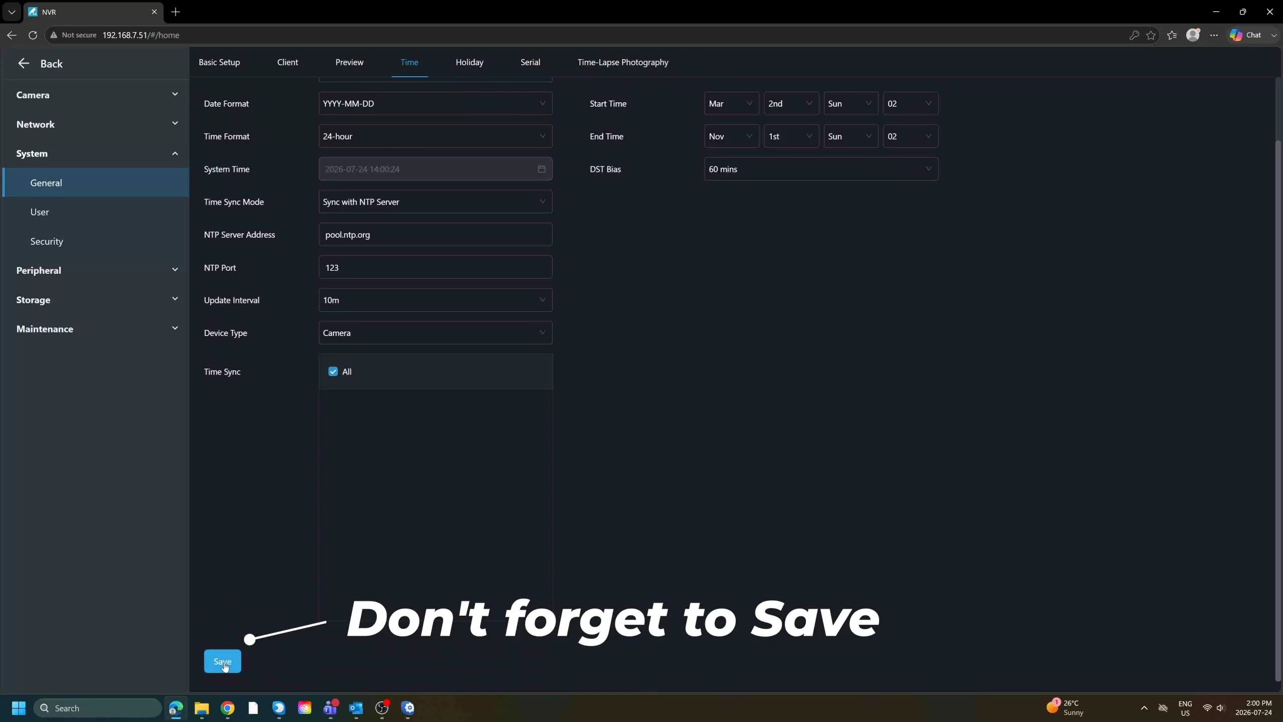 Configuring NTP synchronization with pool.ntp.org guarantees that video timestamps remain accurate for evidence submission.
Surveillance Hard Disk Drives (HDDs) operate under intense 24/7 write stress. Implementing preventive maintenance routines at the hardware and operating system levels prolongs disk lifespan, prevents memory corruption, and maintains system responsiveness.
When installing new surveillance-grade drives (such as Western Digital Purple or Seagate SkyHawk), or reusing drives from prior deployments, perform a full file-system format to clear damaged sectors and write fresh allocation tables.
Running embedded surveillance Linux operating systems indefinitely without maintenance can result in short-term RAM cache clutter. This memory fragmentation can lead to subtle GUI responsiveness drops or slight delays in mobile push notifications.
Navigate to Settings > System > Maintenance. Program an automated reboot schedule for once per week during an off-peak operational window (e.g., Tuesdays at 03:00 AM). Clearing system memory caches keeps push notification pathways running smoothly without missing background recording triggers.
Adding IP cameras depends on whether the cameras are plugged directly into physical PoE ports on the rear of the NVR, or connected to an external PoE network switch located across your local area network (LAN).
Before adopting cameras, configure the NVR's default camera authentication password so it can attempt auto-logins seamlessly:
123456. If you previously initialized your cameras with a custom administrative password, type that custom password into this box.123456 password, utilize the Batch Modify Password function in this menu to update all connected cameras to your custom master password at once.In the new GUI, all discoverable IP devices on your local network automatically populate in the bottom list of the Camera menu, replacing the legacy manual "Auto Search" pop-up window.
If a network camera displays an offline status reading "Network Disconnected", the camera resides on a different network subnet ("different street address") than the NVR's internal network interface.
Think of an IP address like a physical street address. The first three number sets represent the Street Name (e.g., 172.16.0), while the final number represents the specific House Number (e.g., 12). Devices cannot communicate directly unless they reside on the exact same street.
172.16.0.X).192.168.1.50).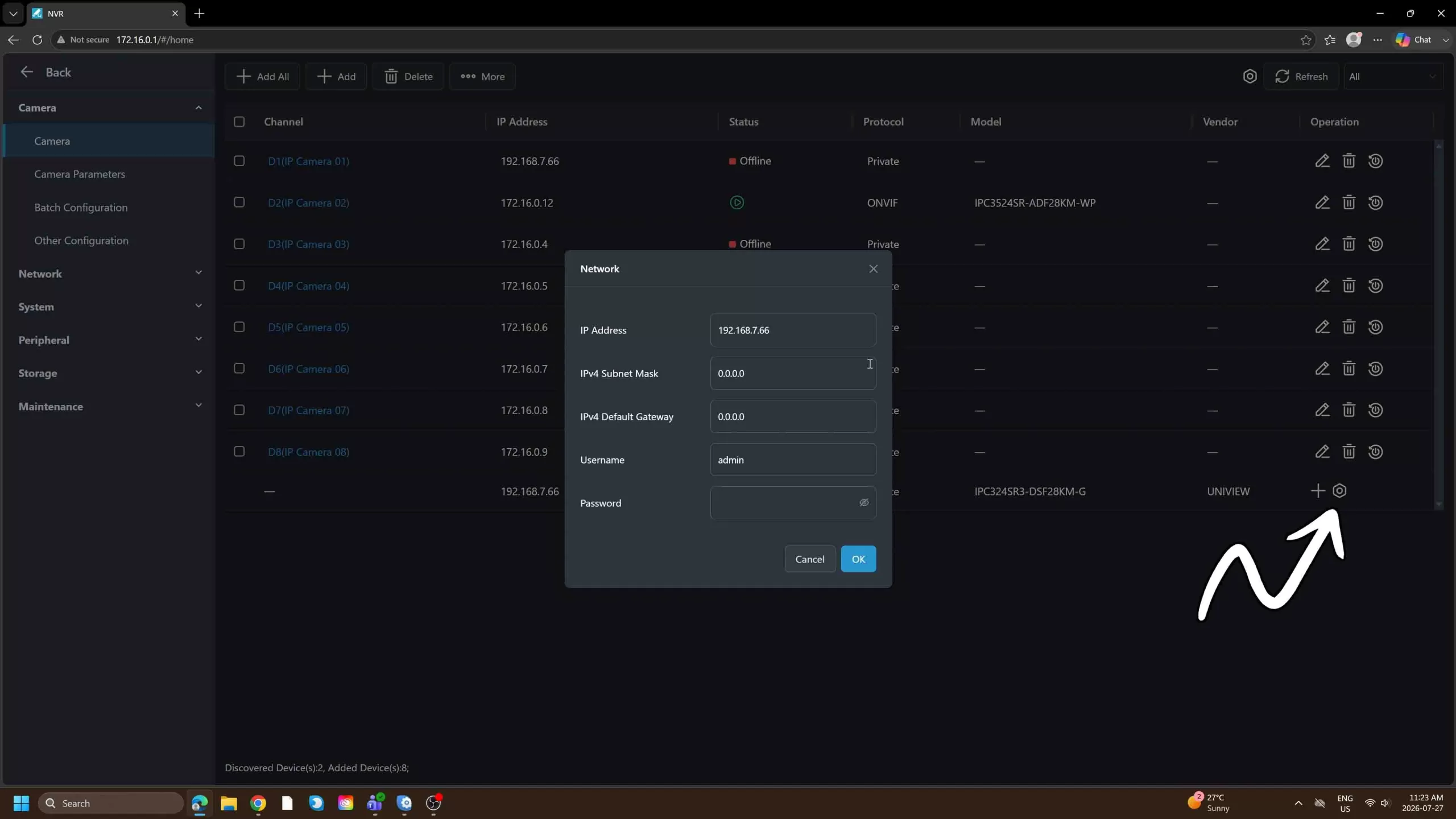 Click the gear icon next to an offline camera to manually adjust its IP subnet.
172.16.0.55), ensuring the final house number is unique on the network.If the camera status displays an error reading "Incorrect username or password", click Modify on that channel, re-enter the camera's current password, and click Save to re-establish the encrypted video handshake.
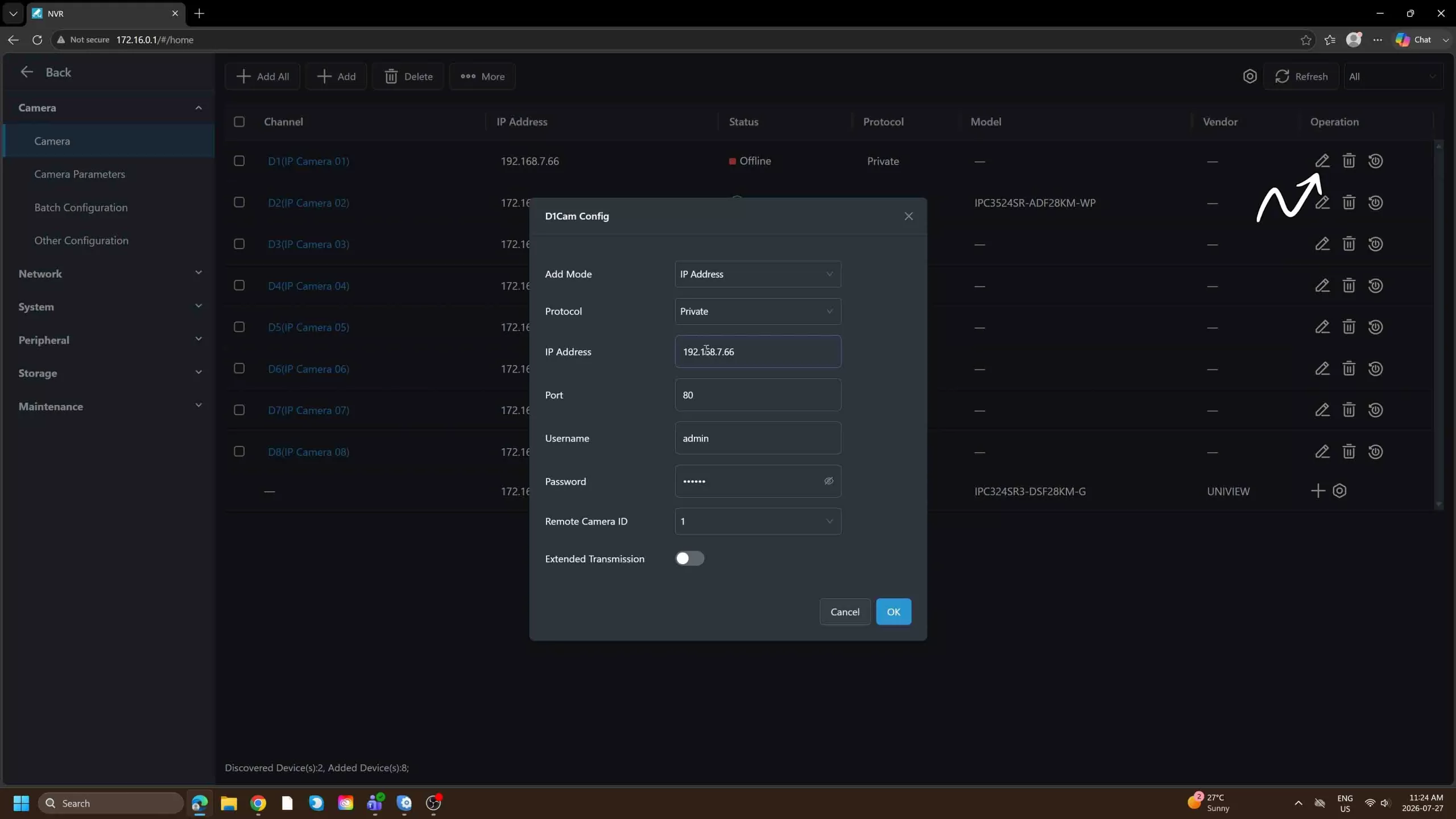 The lower discovery window displays network cameras and allows instant IP subnet modifications via the gear icon.
When adding non-Uniview (third-party) cameras to a Uniview NVR, the system communicates using universal ONVIF (Open Network Video Interface Forum) protocols. Understanding ONVIF profiles determines which advanced features transfer over network streams.
If a third-party camera and the Uniview NVR only share Profile S compatibility, advanced features like H.265 smart encoding or target classification will not operate. Always verify profile compliance across both hardware devices.
Uniview's mobile application, UniEase (and EZCloud portal), enables remote live viewing, notification alerts, and system management over mobile networks without requiring complex router port-forwarding.
Note: This single account login works across both the UniEase mobile smartphone app and the EZCloud desktop portal, removing the need for separate accounts.
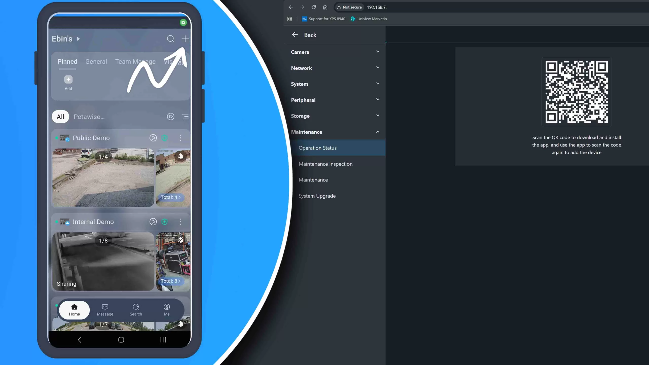 Tap the plus icon in the top right corner to begin pairing a new NVR.
For security, an NVR's hardware QR code can only be scanned and registered by one master account. If an installation technician scans the QR code first under their account, they must use the app's internal Sharing menu to delegate access to your personal user account.
Audio streams offer vital evidentiary context, but camera micro-phones are usually turned off by default out of the box to prevent unintentional privacy compliance issues.
Audio monitoring laws vary by jurisdiction. Many regions enforce strict two-party consent mandates regarding voice recording in public spaces, commercial storefronts, or employee work environments. Posted signage may not fulfill legal requirements in all jurisdictions. Always verify local statutes prior to enabling microphone recording options.
Enabling the microphone on live streams does not automatically write audio data to the hard drive. You must explicitly tell the recorder to bind audio packets into saved video files:
Warning: Audio storage encoding is not retroactive. Footage archived prior to enabling this switch will remain silent and cannot have audio restored.
To maximize hard drive retention days without purchasing extra storage, configure your NVR to log full-resolution video only when motion or smart analytics events are triggered. This approach is useful for indoor spaces or low-traffic perimeter zones during off-peak hours.
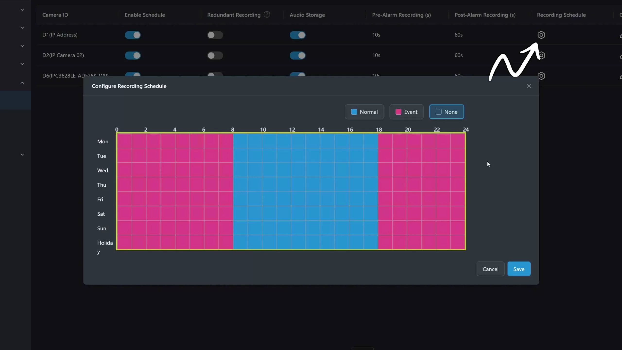 Click the gear icon next to the calendar grid to unlock the scheduling tools.
To ensure motion events capture the actions leading up to a trigger, set up pre-event caching memory:
Setting up red grid schedules tells the NVR when to expect events, but you must also give the system permission to record on trigger. Navigate to the Events menu > Motion Detection > Trigger Action tab. Ensure the checkbox for the corresponding channel is selected under the Recording column. If this box is unchecked, the NVR will detect motion on screen, but will fail to save files to the disk!
Default optical presets rarely deliver ideal performance in challenging environments. Adjusting specialized image processing controls balances harsh glare, low-light noise, and optical orientation.
When a camera faces glass entryways with bright outdoor sunlight competing against dark indoor shadows, subject faces often appear dark and underexposed.
If indoor lighting creates rolling black bars or rapid flickering across your screen, the camera's shutter speed frequency is out of sync with your building's electrical grid frequency. Under Exposure Settings, change the frequency drop-down from Auto to match your electrical grid standard (e.g., 60Hz in North America, 50Hz in Europe).
Standard pixel-change motion detection triggers alerts for irrelevant movements such as heavy rain, falling snow, moving tree shadows, or flying insects. Uniview's Ultra Motion Detection (UMD) applies AI target classification to eliminate false alerts.
For higher perimeter precision, navigate to Events > Smart Event:
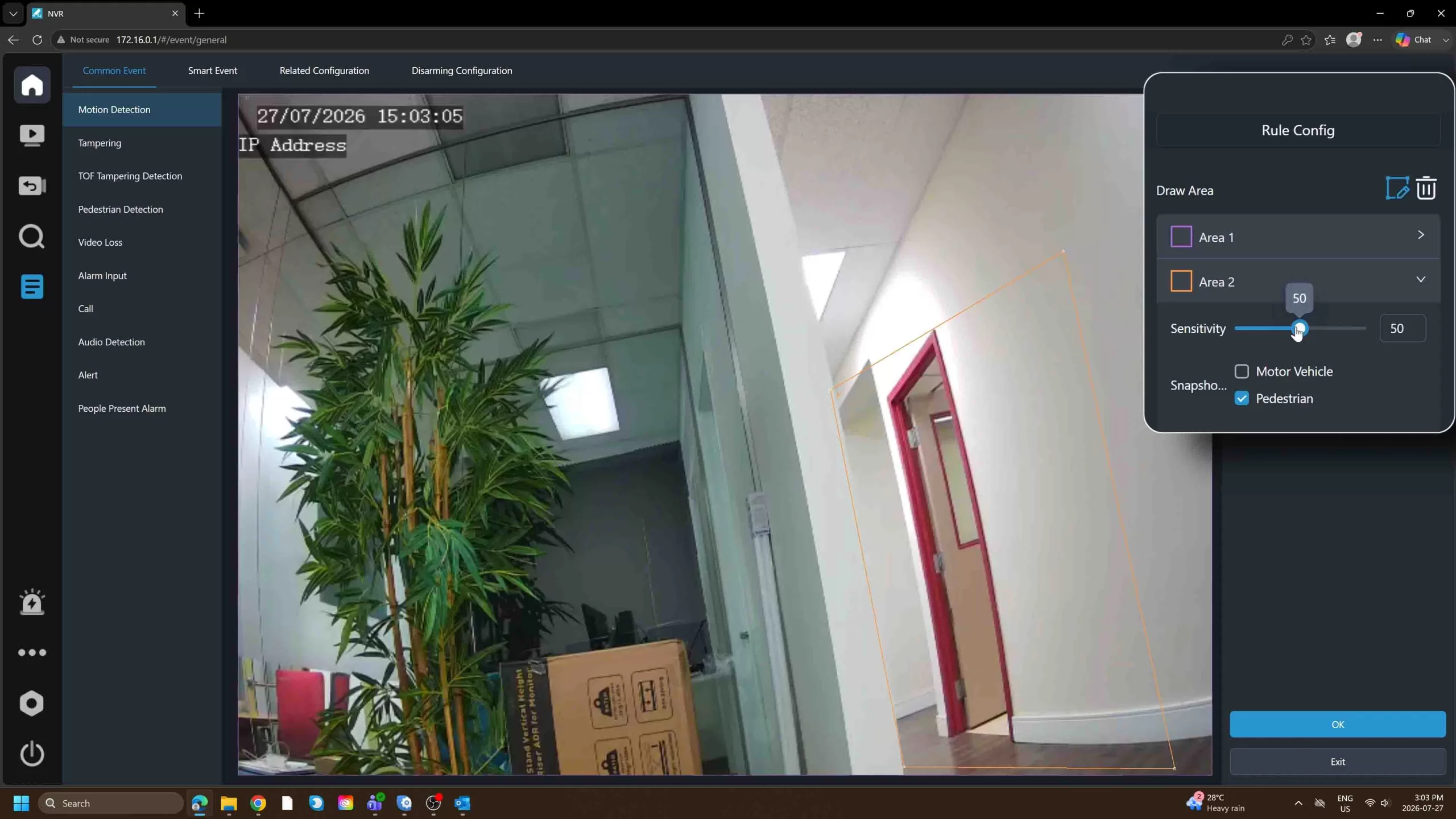 UMD filters out environmental noise like rain or shadows, focusing alerts specifically on human and vehicle targets.
Protecting security systems long-term requires maintaining system software updates, optimizing bandwidth profiles, and securing recorded video metadata against tampering claims.
To access new GUI features, performance fixes, and security patches, regularly check for updates by navigating to Settings > Maintenance > Cloud Update and clicking Check for Update.
If mobile remote video streams freeze or load slowly over cellular data, review your stream encoding profile in Settings > Media > Video:
To protect video evidence against claims of file manipulation or AI video generation, Uniview supports hidden cryptographic watermarking embedded directly into recording frames:
Administrative security dictates that primary master login credentials should never be shared among multiple users, employees, or family members. Instead, delegate access using UniEase account permissions.
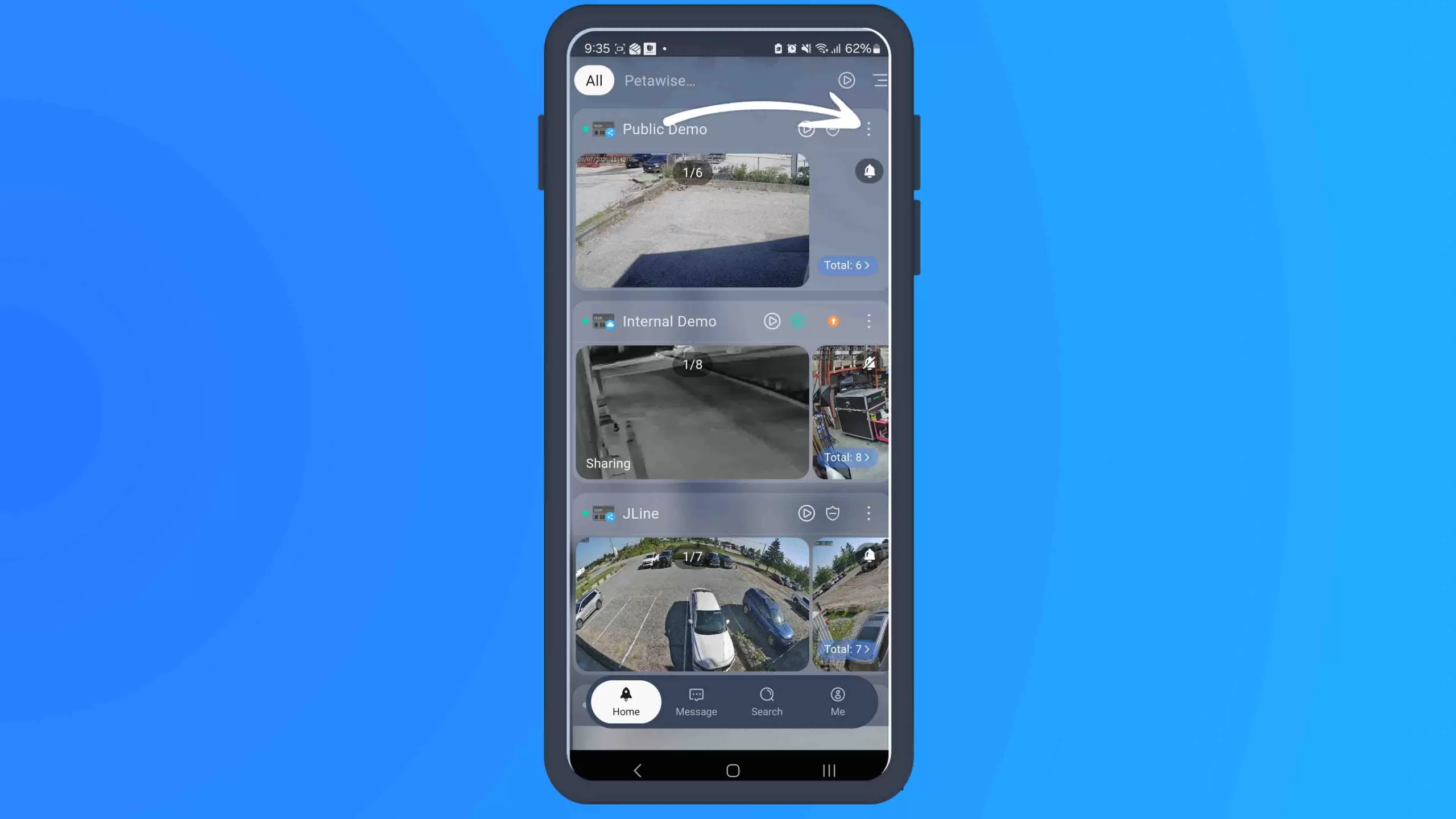 Tap the three dots next to the device name to open the sharing settings.
By following these steps, your Uniview NVR system is initialized, secured, networked, fine-tuned for smart analytics, and prepared for long-term operational stability.
Scan To